O-Ring Machining Specifications
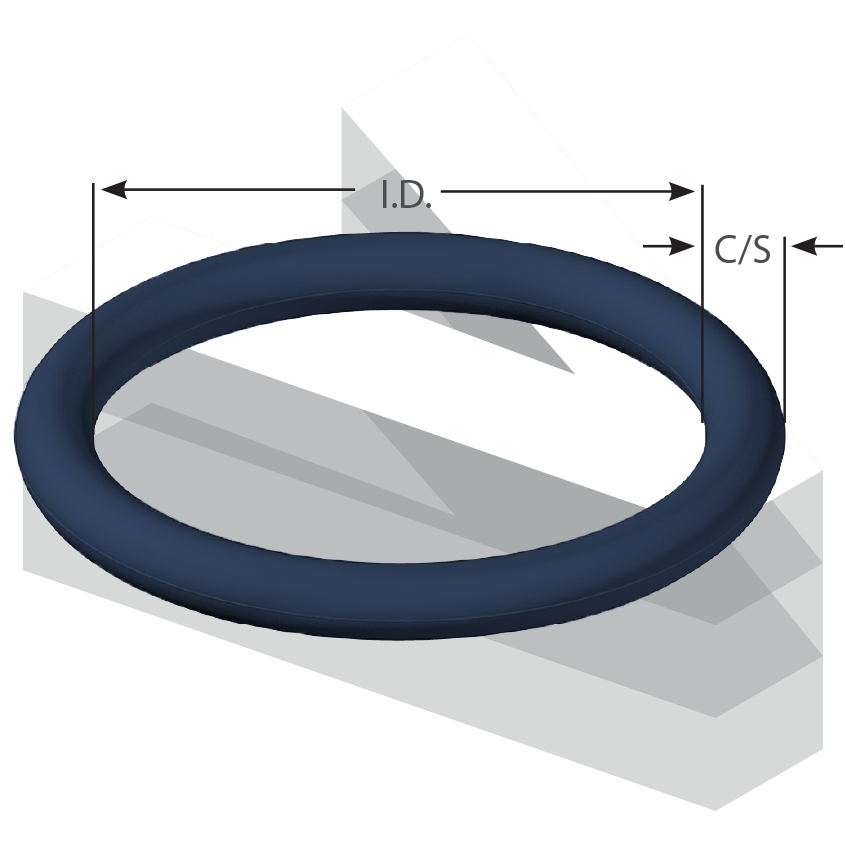
O-Ring Cross-Section
The I.D. and O.D. of an O-ring gland is mainly influenced by diameter of the mating surface of the rod or piston and bore. The cross-section of the O-ring is seen as moderately arbitrary, as there are a few distinct advantages to either a larger or smaller cross-section O-Ring. Listed below are the advantages of small cross-sections and the advantages of large cross sections:
Advantages of Smaller Cross-Section
The main advantages of small O-ring cross-sections incorporate a smaller compact size, lighter weight than larger cross-section O-ring’s, and are less expensive especially in reference to higher cost elastomers like FKM or fluorosilicone. With a smaller cross-section there is less machining required for machined grooves since the groves are smaller. Smaller cross-section O-rings are also resistant to explosive decompression compared to larger cross-section O-rings.
Advantages of Larger Cross-Section
The main advantages of larger cross-section O-rings include being less prone to compression set, less volume swell in liquid based on percentage basis and allows for larger tolerance while maintaining an acceptable compression squeeze and compression ratio over full stack-up range. The larger cross-section O-rings are also less prone to leakage due to contamination (dirt, link, scratches, etc.).
O-Ring Gland Types
Most commonly O-rings are used to prevent the loss of a fluid or gas, however, O-rings are also useful as dust seals, drive belts, or on rotating shafts. O-rings follow the following arrangements:
Piston Configuration

Rod Configuration

Face Type Configuration

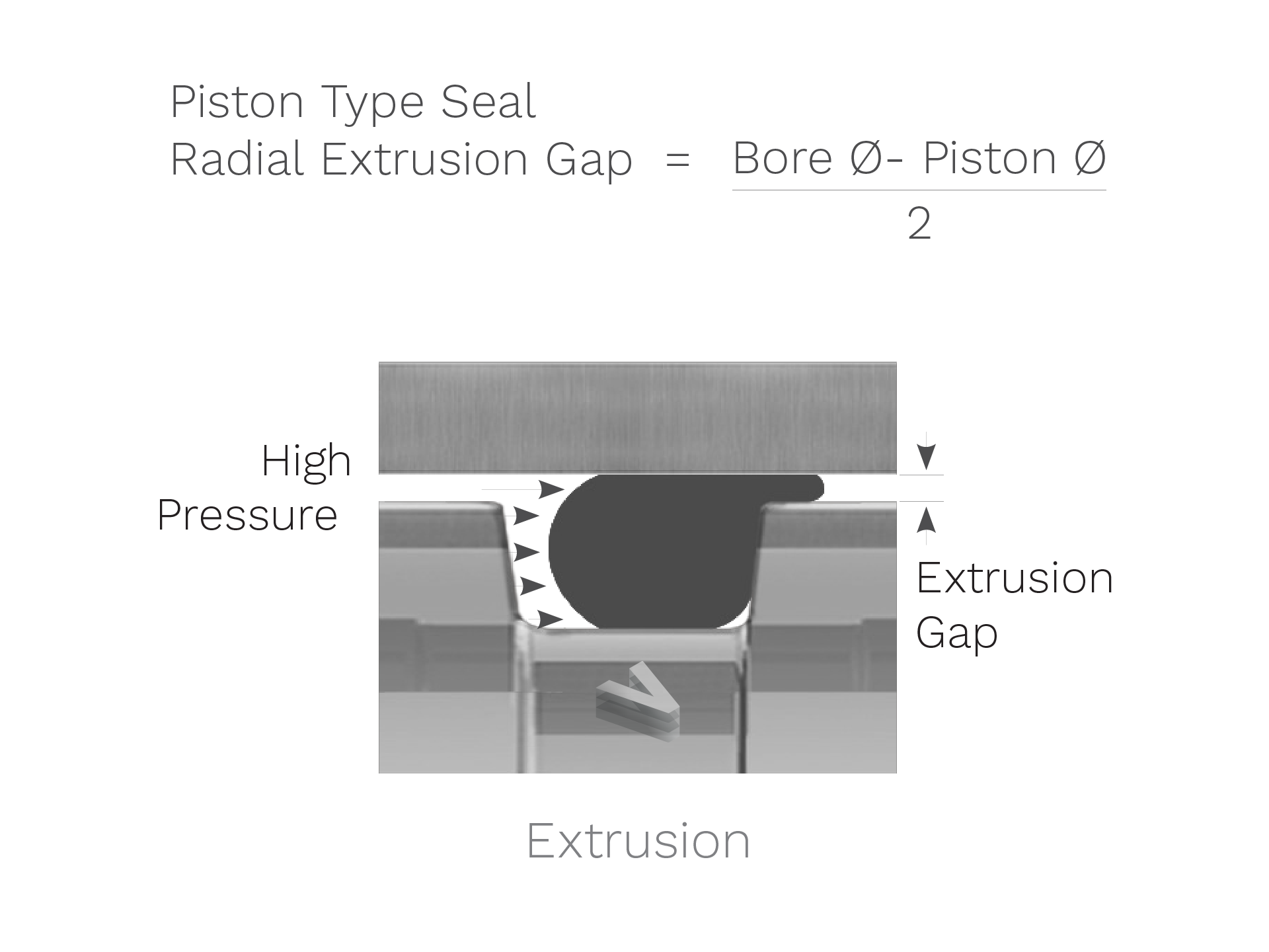
Extrusion Gap
Where there is a gap between the piston and the bore for a piston type seal or between the rod and the bore for a rod type seal, extrusion becomes a concern for radial seals. Extrusion gaps are not commonly a concern for face type seals where the metal parts to be sealed are in contact line-to-line. Higher pressures and especially for softer O-ring elastomers, higher pressure becomes the key issues. The O-ring can be completely forced by the pressure into the small gap between the piston (or rod) and the bore. This is unless the bore and the piston (or rod) are ensured to remain concentric by the hardware, we have to assume that entire possible gap can shift to one side. For additional detail, please see the diagram below.

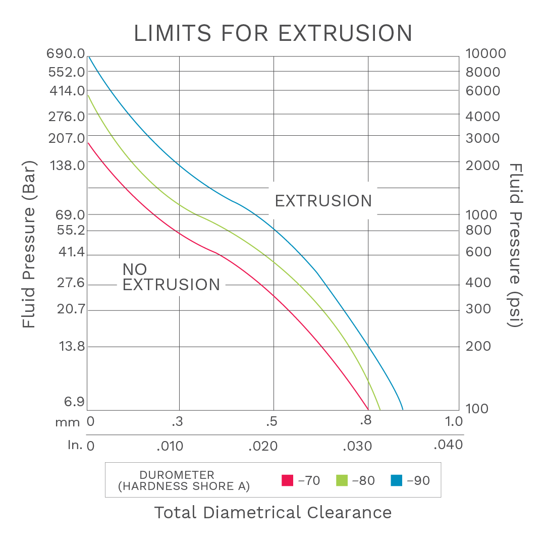
Limits for Extrusion
O-ring extrusion can be countered by increasing the durometer rating the O-ring. Please note that when you increase the durometer, theO-ring can become less malleable. You can also use anti-extrusion devices. An anti-extrusion device is a thin ring composed of hard plastic such as PTFE, Nylon and PEEK. Once in place, these rings will provide essentially zero clearance.
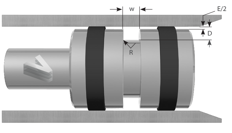
Groove Dimensions - ISO 3601
Static Radial Applications

| O-Ring C/S | D Groove Depth | Squeeze Inches | Squeeze % | E Diametrical Clearance Max. | W*Groove Width +0.010/-0.000 No Back-Up Ring | W*Groove Width +0.010/-0.000 One Back-Up Ring | W*Groove Width +0.010/-0.000 Two Back-Up Ring | R Groove Radius |
|---|---|---|---|---|---|---|---|---|
| 0.070 | 0.049 - 0.057 | 0.010 - 0.025 | 14 - 35 | 0.004 | 0.110 | 0.165 | 0.220 | 0.008 - 0.016 |
| 0.103 | 0.075 - 0.087 | 0.013 - 0.031 | 13 - 30 | 0.005 | 0.150 | 0.205 | 0.260 | 0.008 - 0.016 |
| 0.139 | 0.101 - 0.117 | 0.018 - 0.042 | 13 - 30 | 0.006 | 0.197 | 0.252 | 0.307 | 0.016 - 0.031 |
| 0.210 | 0.156 - 0.180 | 0.025 - 0.059 | 12 - 28 | 0.006 | 0.283 | 0.354 | 0.429 | 0.016 - 0.031 |
| 0.275 | 0.212 - 0.242 | 0.028 - 0.069 | 10 - 25 | 0.007 | 0.374 | 0.484 | 0.594 | 0.031 - 0.047 |
Static Axial (Face) Applications

| O-Ring C/S | D Groove Depth +0.004/-0.000 | Squeeze % | W Groove Width +0.008/-0.000 Hydraulic | W Groove Width +0.008/-0.000 Pneumatic/Vacuum | R Groove Radius |
|---|---|---|---|---|---|
| 0.070 | 0.051 | 21 - 36 | 0.126 | 0.114 | 0.008 - 0.016 |
| 0.103 | 0.079 | 19 - 30 | 0.157 | 0.142 | 0.008 - 0.016 |
| 0.139 | 0.106 | 17 - 26 | 0.209 | 0.189 | 0.016 - 0.031 |
| 0.210 | 0.165 | 15 - 23 | 0.299 | 0.276 | 0.016 - 0.031 |
| 0.275 | 0.224 | 13 - 20 | 0.354 | 0.335 | 0.031 - 0.047 |
Reciprocating Applications
| O-Ring C/S | D Groove Depth Hydraulic | D Groove Depth Pneumatic | Squeeze Hydraulic Inches | Squeeze Hydraulic % | Squeeze Pneumatic Inches | Squeeze Pneumatic % | E Diametrical Clearance Max. | w* Groove Width +0.010/-0.000 No Back-Up Ring | w* Groove Width +0.010/-0.000 One Back-Up Ring | w* Groove Width +0.010/-0.000 Two Back-Up Rings | R Groove Radius |
|---|---|---|---|---|---|---|---|---|---|---|---|
| 0.070 | 0.054 - 0.058 | 0.056 - 0.060 | 0.009 - 0.019 | 13 - 27 | 0.007 - 0.017 | 10 - 24 | 0.004 | 0.110 | 0.165 | 0.220 | 0.008 - 0.016 |
| 0.103 | 0.081 - 0.088 | 0.083 - 0.092 | 0.012 - 0.025 | 12 - 24 | 0.008 - 0.023 | 8 - 22 | 0.005 | 0.150 | 0.205 | 0.260 | 0.008 - 0.016 |
| 0.139 | 0.112 - 0.120 | 0.115 - 0.125 | 0.015 - 0.031 | 12 - 22 | 0.010 - 0.028 | 7 - 20 | 0.006 | 0.197 | 0.252 | 0.307 | 0.016 - 0.031 |
| 0.210 | 0.173 - 0.182 | 0.177 - 0.190 | 0.023 - 0.042 | 12 - 20 | 0.015 - 0.038 | 7 - 18 | 0.006 | 0.283 | 0.354 | 0.429 | 0.016 - 0.031 |
| 0.275 | 0.229 - 0.244 | 0.234 - 0.253 | 0.025 - 0.052 | 9 - 19 | 0.017 - 0.047 | 6 - 17 | 0.007 | 0.374 | 0.484 | 0.594 | 0.031 - 0.047 |
Tolerances for Non-Standard O-Rings
Reciprocating Applications
| Cross Section (mm) | Tolerance (mm) |
|---|---|
| 0.80 < C/S ≤ 3.15 | ± 0.08 |
| 3.15 < C/S ≤ 4.50 | ± 0.10 |
| 4.50 < C/S ≤ 6.30 | ± 0.13 |
| 6.30 < C/S ≤ 8.40 | ± 0.15 |
| Inside Diameter (mm) | Tolerance (mm) |
|---|---|
| 0.68 to 1.53 | ± 0.10 |
| 1.54 to 11.69 | ± 0.13 |
| 11.70 to 13.46 | ± 0.15 |
| 13.47 to 17.53 | ± 0.18 |
| 17.54 to 20.57 | ± 0.20 |
| 20.58 to 23.88 | ± 0.23 |
| 23.89 to 28.70 | ± 0.25 |
| 28.71 to 35.56 | ± 0.30 |
| 35.57 to 43.18 | ± 0.36 |
| 43.19 to 50.80 | ± 0.41 |
| Inside Diameter (mm) | Tolerance (mm) |
|---|---|
| 50.81 to 58.42 | ± 0.46 |
| 58.43 to 66.55 | ± 0.51 |
| 66.56 to 74.93 | ± 0.56 |
| 74.94 to 83.57 | ± 0.61 |
| 83.58 to 92.20 | ± 0.66 |
| 92.21 to 101.60 | ± 0.71 |
| 101.61 to 117.35 | ± 0.76 |
| 117.36 to 141.22 | ± 0.89 |
| 141.23 to 166.37 | ± 1.02 |
| 166.38 to 192.02 | ± 1.14 |
| Inside Diameter (mm) | Tolerance (mm) |
|---|---|
| 192.03 to 218.69 | ± 1.27 |
| 218.70 to 253.37 | ± 1.40 |
| 253.38 to 289.56 | ± 1.52 |
| 289.57 to 347.98 | ± 1.78 |
| 347.99 to 408.94 | ± 2.03 |
| 408.95 to 472.44 | ± 2.29 |
| 472.45 to 571.50 | ± 2.54 |
| 571.51 to 711.20 | ± 3.05 |
| 711.21 to 855.98 | ± 3.56 |
| 855.99 to 1005.84 | ± 4.06 |
| 1005.85 to 1163.32 | ± 4.57 |
| 1163.33 to 1320.80 | ± 5.08 |
Have a question?
Contact Us
For more information on how Varigate Technologies can help you today, contact us to find out how we can help you and your specific need.
Looking for this?
VTI Carbide